本文介绍基于Python语言中gdal模块,对遥感影像数据进行栅格读取与计算,同时基于QA波段对像元加以筛选、掩膜的操作。
本文所要实现的需求具体为:现有自行计算的全球叶面积指数(LAI).tif格式栅格产品(下称“自有产品”),为了验证其精确度,需要与已有学者提出的成熟产品——GLASS全球LAI.hdf格式栅格产品(下称“GLASS产品”)进行做差对比;其中,自有产品除了LAI波段外,还有一个质量评估波段(QA),即自有产品在后期使用时,还需结合QA波段进行筛选、掩膜等处理。其中,二者均为基于MODIS hv分幅的产品。
本文分为两部分,第一部分为代码的详细分段讲解,第二部分为完整代码。
1 代码分段讲解
1.1 模块与路径准备
首先,需要对用到的模块与存放栅格图像的各类路径加以准备。
import os
import copy
import numpy as np
import pylab as plt
from osgeo import gdal

# rt_file_path="G:/Postgraduate/LAI_Glass_RTlab/Rc_Lai_A2018161_h12v03.tif"
# gl_file_path="G:/Postgraduate/LAI_Glass_RTlab/GLASS01E01.V50.A2018161.h12v03.2020323.hdf"
# out_file_path="G:/Postgraduate/LAI_Glass_RTlab/test.tif"
rt_file_path="I:/LAI_RTLab/A2018161/"
gl_file_path="I:/LAI_Glass/2018161/"
out_file_path="I:/LAI_Dif/"
其中,rt_file_path为自有产品的存放路径,gl_file_path为GLASS产品的存放路径,out_file_path为最终二者栅格做完差值处理后结果的存放路径。
1.2 栅格图像文件名读取与配对
接下来,需要将全部待处理的栅格图像用os.listdir()进行获取,并用for循环进行循环批量处理操作的准备。
rt_file_list=os.listdir(rt_file_path)
for rt_file in rt_file_list:
    file_name_split=rt_file.split("_")
    rt_hv=file_name_split[3][:-4]

    gl_file_list=os.listdir(gl_file_path)
    for gl_file in gl_file_list:
        if rt_hv in gl_file:
            rt_file_tif_path=rt_file_path+rt_file
            gl_file_tif_path=gl_file_path+gl_file
其中,由于本文需求是对两种产品做差,因此首先需要结合二者的hv分幅编号,将同一分幅编号的两景遥感影像放在一起;因此,依据自有产品文件名的特征,选择.split()进行字符串分割,并随后截取获得遥感影像的hv分幅编号。
1.3 输出文件名称准备
前述1.1部分已经配置好了输出文件存放的路径,但是还没有进行输出文件文件名的配置;因此这里我们需要配置好每一个做差后的遥感影像的文件存放路径与名称。其中,我们就直接以遥感影像的hv编号作为输出结果文件名。
            DRT_out_file_path=out_file_path+"DRT/"
            if not os.path.exists(DRT_out_file_path):
                os.makedirs(DRT_out_file_path)
            DRT_out_file_tif_path=os.path.join(DRT_out_file_path,rt_hv+".tif")

            eco_out_file_path=out_file_path+"eco/"
            if not os.path.exists(eco_out_file_path):
                os.makedirs(eco_out_file_path)
            eco_out_file_tif_path=os.path.join(eco_out_file_path,rt_hv+".tif")

            wat_out_file_path=out_file_path+"wat/"
            if not os.path.exists(wat_out_file_path):
                os.makedirs(wat_out_file_path)
            wat_out_file_tif_path=os.path.join(wat_out_file_path,rt_hv+".tif")

            tim_out_file_path=out_file_path+"tim/"
            if not os.path.exists(tim_out_file_path):
                os.makedirs(tim_out_file_path)
            tim_out_file_tif_path=os.path.join(tim_out_file_path,rt_hv+".tif")
这一部分代码分为了四个部分,是因为自有产品的LAI是分别依据四种算法得到的,在做差时需要每一种算法分别和GLASS产品进行相减,因此配置了四个输出路径文件夹。
1.4 栅格文件数据与信息读取
接下来,利用gdal模块对.tif与.hdf等两种栅格图像加以读取。
            rt_raster=gdal.Open(rt_file_path+rt_file)
            rt_band_num=rt_raster.RasterCount
            rt_raster_array=rt_raster.ReadAsArray()
            rt_lai_array=rt_raster_array[0]
            rt_qa_array=rt_raster_array[1]
            rt_lai_band=rt_raster.GetRasterBand(1)
            # rt_lai_nodata=rt_lai_band.GetNoDataValue()
            # rt_lai_nodata=32767
            # rt_lai_mask=np.ma.masked_equal(rt_lai_array,rt_lai_nodata)
            rt_lai_array_mask=np.where(rt_lai_array>30000,np.nan,rt_lai_array)
            rt_lai_array_fin=rt_lai_array_mask*0.001

            gl_raster=gdal.Open(gl_file_path+gl_file)
            gl_band_num=gl_raster.RasterCount
            gl_raster_array=gl_raster.ReadAsArray()
            gl_lai_array=gl_raster_array
            gl_lai_band=gl_raster.GetRasterBand(1)
            gl_lai_array_mask=np.where(gl_lai_array>1000,np.nan,gl_lai_array)
            gl_lai_array_fin=gl_lai_array_mask*0.01

            row=rt_raster.RasterYSize
            col=rt_raster.RasterXSize
            geotransform=rt_raster.GetGeoTransform()
            projection=rt_raster.GetProjection()
首先,以上述代码的第一段为例进行讲解。其中,gdal.Open()读取栅格图像;.RasterCount获取栅格图像波段数量;.ReadAsArray()将栅格图像各波段的信息读取为Array格式,当波段数量大于1时,其共有三维,第一维为波段的个数;rt_raster_array[0]表示取Array中的第一个波段,在本文中也就是自有产品的LAI波段;rt_qa_array=rt_raster_array[1]则表示取出第二个波段,在本文中也就是自有产品的QA波段;.GetRasterBand(1)表示获取栅格图像中的第一个波段(注意,这里序号不是从0开始而是从1开始);np.where(rt_lai_array>30000,np.nan,rt_lai_array)表示利用np.where()函数对Array中第一个波段中像素>30000加以选取,并将其设置为nan,其他值不变。这一步骤是消除图像中填充值、Nodata值的方法。最后一句*0.001是将图层原有的缩放系数复原。
其次,上述代码第三段为获取栅格行、列数与投影变换信息。
1.5 差值计算与QA波段筛选
接下来,首先对自有产品与GLASS产品加以做差操作,随后需要对四种算法分别加以提取。
            lai_dif=rt_lai_array_fin-gl_lai_array_fin
            lai_dif=lai_dif*1000

            rt_qa_array_bin=copy.copy(rt_qa_array)
            rt_qa_array_row,rt_qa_array_col=rt_qa_array.shape
            for i in range(rt_qa_array_row):
                for j in range(rt_qa_array_col):
                    rt_qa_array_bin[i][j]="{:012b}".format(rt_qa_array_bin[i][j])[-4:]

            # DRT_pixel_pos=np.where((rt_qa_array_bin>=100) & (rt_qa_array_bin==11))
            # eco_pixel_pos=np.where((rt_qa_array_bin=100) | (rt_qa_array_bin==11),
                                       np.nan,lai_dif)
            eco_lai_dif_array=np.where((rt_qa_array_bin
其中,上述代码前两句为差值计算与数据化整。将数据转换为整数,可以减少结果数据图层的数据量(因为不需要存储小数了)。
随后,开始依据QA波段进行数据筛选与掩膜。其实各类遥感影像(例如MODIS、Landsat等)的QA波段都是比较近似的:通过一串二进制码来表示遥感影像的质量、信息等,其中不同的比特位往往都代表着一种特性。例如下图所示为Landsat Collection 2 Level-2的QA波段含义。
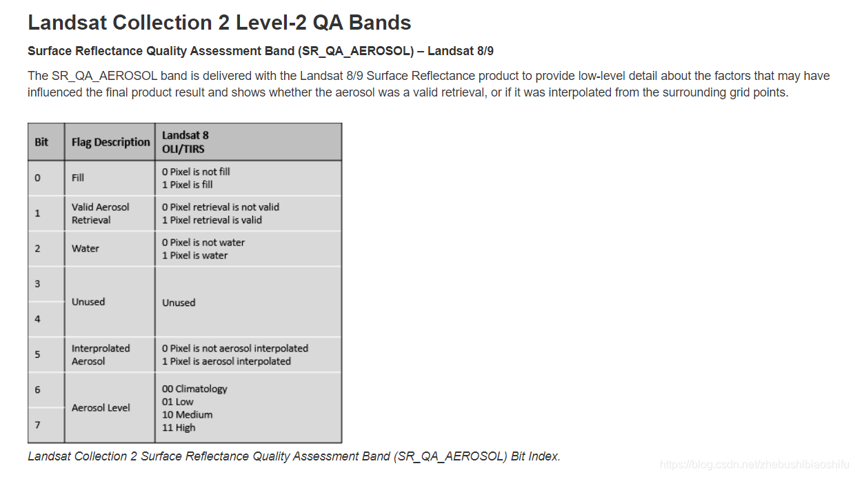
在这里,QA波段原本为十进制(一般遥感影像为了节省空间,QA波段都是写成十进制的形式),因此需要将其转换为二进制;随后通过获取指定需要的二进制数据位数(在本文中也就是能确定自有产品中这一像素来自于哪一种算法的二进制位数),从而判断这一像素所得LAI是通过哪一种算法得到的,从而将每种算法对应的像素分别放在一起处理。DRT_lai_dif_array等四个变量分别表示四种算法中,除了自己这一种算法得到的像素之外的其他所有像素;之所以选择这种方式,是因为后期我们可以将其直接掩膜掉,那么剩下的就是这种算法自身的像素了。
其中,上述代码注释掉的plt相关内容可以实现绘制空间分布图,大家感兴趣可以尝试使用。
1.6 结果栅格文件写入与保存
接下来,将我们完成上述差值计算与依据算法进行筛选后的图像保存。
            driver=gdal.GetDriverByName("Gtiff")
            out_DRT_lai=driver.Create(DRT_out_file_tif_path,row,col,1,gdal.GDT_Float32)
            out_DRT_lai.SetGeoTransform(geotransform)
            out_DRT_lai.SetProjection(projection)
            out_DRT_lai.GetRasterBand(1).WriteArray(DRT_lai_dif_array)
            out_DRT_lai=None

            driver=gdal.GetDriverByName("Gtiff")
            out_eco_lai=driver.Create(eco_out_file_tif_path,row,col,1,gdal.GDT_Float32)
            out_eco_lai.SetGeoTransform(geotransform)
            out_eco_lai.SetProjection(projection)
            out_eco_lai.GetRasterBand(1).WriteArray(eco_lai_dif_array)
            out_eco_lai=None

            driver=gdal.GetDriverByName("Gtiff")
            out_wat_lai=driver.Create(wat_out_file_tif_path,row,col,1,gdal.GDT_Float32)
            out_wat_lai.SetGeoTransform(geotransform)
            out_wat_lai.SetProjection(projection)
            out_wat_lai.GetRasterBand(1).WriteArray(wat_lai_dif_array)
            out_wat_lai=None

            driver=gdal.GetDriverByName("Gtiff")
            out_tim_lai=driver.Create(tim_out_file_tif_path,row,col,1,gdal.GDT_Float32)
            out_tim_lai.SetGeoTransform(geotransform)
            out_tim_lai.SetProjection(projection)
            out_tim_lai.GetRasterBand(1).WriteArray(tim_lai_dif_array)
            out_tim_lai=None

            print(rt_hv)
其中,.GetDriverByName("Gtiff")表示保存为.tif格式的GeoTIFF文件;driver.Create(DRT_out_file_tif_path,row,col,1,gdal.GDT_Float32)表示按照路径、行列数、波段数与数据格式等建立一个新的栅格图层,作为输出图层的框架;其后表示分别将地理投影转换信息与像素具体数值分别赋予这一新建的栅格图层;最后=None表示将其从内存空间中释放,完成写入与保存工作。
2 完整代码
本文所需完整代码如下:
# -*- coding: utf-8 -*-
"""
Created on Thu Jul 15 19:36:15 2021

@author: fkxxgis
"""

import os
import copy
import numpy as np
import pylab as plt
from osgeo import gdal

# rt_file_path="G:/Postgraduate/LAI_Glass_RTlab/Rc_Lai_A2018161_h12v03.tif"
# gl_file_path="G:/Postgraduate/LAI_Glass_RTlab/GLASS01E01.V50.A2018161.h12v03.2020323.hdf"
# out_file_path="G:/Postgraduate/LAI_Glass_RTlab/test.tif"
rt_file_path="I:/LAI_RTLab/A2018161/"
gl_file_path="I:/LAI_Glass/2018161/"
out_file_path="I:/LAI_Dif/"

rt_file_list=os.listdir(rt_file_path)
for rt_file in rt_file_list:
    file_name_split=rt_file.split("_")
    rt_hv=file_name_split[3][:-4]

    gl_file_list=os.listdir(gl_file_path)
    for gl_file in gl_file_list:
        if rt_hv in gl_file:
            rt_file_tif_path=rt_file_path+rt_file
            gl_file_tif_path=gl_file_path+gl_file

            DRT_out_file_path=out_file_path+"DRT/"
            if not os.path.exists(DRT_out_file_path):
                os.makedirs(DRT_out_file_path)
            DRT_out_file_tif_path=os.path.join(DRT_out_file_path,rt_hv+".tif")

            eco_out_file_path=out_file_path+"eco/"
            if not os.path.exists(eco_out_file_path):
                os.makedirs(eco_out_file_path)
            eco_out_file_tif_path=os.path.join(eco_out_file_path,rt_hv+".tif")

            wat_out_file_path=out_file_path+"wat/"
            if not os.path.exists(wat_out_file_path):
                os.makedirs(wat_out_file_path)
            wat_out_file_tif_path=os.path.join(wat_out_file_path,rt_hv+".tif")

            tim_out_file_path=out_file_path+"tim/"
            if not os.path.exists(tim_out_file_path):
                os.makedirs(tim_out_file_path)
            tim_out_file_tif_path=os.path.join(tim_out_file_path,rt_hv+".tif")

            rt_raster=gdal.Open(rt_file_path+rt_file)
            rt_band_num=rt_raster.RasterCount
            rt_raster_array=rt_raster.ReadAsArray()
            rt_lai_array=rt_raster_array[0]
            rt_qa_array=rt_raster_array[1]
            rt_lai_band=rt_raster.GetRasterBand(1)
            # rt_lai_nodata=rt_lai_band.GetNoDataValue()
            # rt_lai_nodata=32767
            # rt_lai_mask=np.ma.masked_equal(rt_lai_array,rt_lai_nodata)
            rt_lai_array_mask=np.where(rt_lai_array>30000,np.nan,rt_lai_array)
            rt_lai_array_fin=rt_lai_array_mask*0.001

            gl_raster=gdal.Open(gl_file_path+gl_file)
            gl_band_num=gl_raster.RasterCount
            gl_raster_array=gl_raster.ReadAsArray()
            gl_lai_array=gl_raster_array
            gl_lai_band=gl_raster.GetRasterBand(1)
            gl_lai_array_mask=np.where(gl_lai_array>1000,np.nan,gl_lai_array)
            gl_lai_array_fin=gl_lai_array_mask*0.01

            row=rt_raster.RasterYSize
            col=rt_raster.RasterXSize
            geotransform=rt_raster.GetGeoTransform()
            projection=rt_raster.GetProjection()

            lai_dif=rt_lai_array_fin-gl_lai_array_fin
            lai_dif=lai_dif*1000

            rt_qa_array_bin=copy.copy(rt_qa_array)
            rt_qa_array_row,rt_qa_array_col=rt_qa_array.shape
            for i in range(rt_qa_array_row):
                for j in range(rt_qa_array_col):
                    rt_qa_array_bin[i][j]="{:012b}".format(rt_qa_array_bin[i][j])[-4:]

            # DRT_pixel_pos=np.where((rt_qa_array_bin>=100) & (rt_qa_array_bin==11))
            # eco_pixel_pos=np.where((rt_qa_array_bin=100) | (rt_qa_array_bin==11),
                                       np.nan,lai_dif)
            eco_lai_dif_array=np.where((rt_qa_array_bin
到此这篇关于Python利用GDAL模块实现读取栅格数据并对指定数据加以筛选掩膜的文章就介绍到这了,更多相关Python GDAL读取栅格数据内容请搜索IT俱乐部以前的文章或继续浏览下面的相关文章希望大家以后多多支持IT俱乐部!